How to construct a section of a polyhedron using three points. Learning to build sections
Practical lesson: “Parallelepiped. Construction of sections of a parallelepiped."
1. Target practical work : . To consolidate knowledge of theoretical material about polyhedra,problem solving skills in construction of sections, ability to analyze a drawing.
2. Didactic equipment for practical work : Workstation, models and developments of polyhedra, measuring instruments, scissors, glue, thick paper.
Time:2 hours
Tasks for work:
Task 1
Construct a section of the parallelepiped ABCDA 1 B 1 C 1 D 1 plane passing through points M, N, P lying on lines, respectively, A 1 B 1, AD, DC
Sample and the sequence of solving the problem:
1.Points N and P lie in the section plane and in the plane of the lower base of the parallelepiped. Let's construct a straight line passing through these points. This straight line is the trace of the cutting plane onto the plane of the base of the parallelepiped.
2. Let us continue the straight line on which side AB of the parallelepiped lies. Lines AB and NP intersect at some point S. This point belongs to the section plane.
3. Since point M also belongs to the section plane and intersects line AA 1 at some point X.
4.Points X and N lie in the same plane of face AA 1 D 1 D, connect them and get straight line XN.
5. Since the planes of the faces of the parallelepiped are parallel, then through the point M we can draw a straight line to the face A 1 B 1 C 1 D 1 , parallel to the line NP. This line will intersect side B 1 WITH 1 at point Y.
6. Similarly, draw straight line YZ, parallel to straight line XN. We connect Z with P and get the desired section - MYZPNX.
Task 2
Option 1. Construct a section of the parallelepiped АВСDA1В1С1D1 by the plane defined by the following pointsM, NAndP
Level 1: All three points lie on the edges emerging from vertex A
Level 2.Mlies in the face AA1D1D,Nlies on the face AA1B1B,Plies in the face CC1D1D.
Level 3.Mlies on the diagonal B1D,Nlies on the diagonal AC1,Plies on the edge C1D1.
Option2.Construct a section of the parallelepiped ABCDA1B1C1D1 by a plane passing through the line DQ, where point Q lies on the edge CC1 and point P, defined as follows
Level 1: All three points lie on the edges emerging from vertex C
Level 2: M lies on the continuation of edge A1B1, and point A1 is located between points B1 and P.
Level 3: P lies on the diagonal B1D
Work order:
1.Study theoretical material on the following topics:
Parallelepiped.
Right parallelepiped.
Inclined parallelepiped.
Opposite faces of a parallelepiped.
Properties of parallelepiped diagonals.
Pthe concept of a cutting plane and the rules for its construction.
What types of polygons are obtained in the section of a cube and parallelepiped.
2. BuildparallelepipedABCDA 1 B 1 C 1 D 1
3. Analyze the solution to problem No. 1
4.Consistently build a sectionparallelepipedABCDA 1 B 1 C 1 D 1 plane passing through points P, Q, R of problem No. 1.
5.Construct three more parallelepipeds and select sections for problems of levels 1, 2, and 3 on them
Evaluation criteria :
Literature: Atanasyan L.S. Geometry: Textbook for 10-11 grades. general education institutions. L.S. Atanasyan, V.F. Butuzov, S.B. Kodomtsev et al. - M.: Education, 2010 Ziv B.G. Geometry problems: A manual for students of grades 7-11. general education institutions. / B.G. Ziv, V.M. Mailer, A.G. Bakhansky. - M.: Education, 2010. V. N. Litvinenko Tasks for the development of spatial concepts. Book for teachers. - M.: Education, 2010
Didactic material to the task practical lesson
To task No. 1:
Some possible sections:

Construct sections of a parallelepiped with a plane passing through these points


CONSTRUCTION OF SECTIONS AND SECTIONS ON DRAWINGS
The formation of a part drawing is carried out by sequentially adding the necessary projections, sections and sections. Initially, a custom view is created with a user-specified model, and the model orientation is set that is most suitable for the main view. Next, using this and the following views, the necessary cuts and sections are created.
The main view (front view) is selected so that it gives the most complete idea of the shapes and dimensions of the part.
Sections in drawings
Depending on the position of the cutting plane, the following types of cuts are distinguished:
A) horizontal, if the cutting plane is located parallel to the horizontal plane of projections;
B) vertical, if the cutting plane is perpendicular to the horizontal plane of projections;
C) inclined - the cutting plane is inclined to the projection planes.
Vertical sections are divided into:
· frontal - the cutting plane is parallel to the frontal plane of projections;
·
profile - the cutting plane is parallel to the profile plane of projections.
Depending on the number of secant planes, the cuts are:
· simple - with one cutting plane (Fig. 107);
·
complex - with two or more cutting planes (Fig. 108)
The standard provides for the following types of Complex cuts:
· stepped, when the cutting planes are parallel (Fig. 108 a) and broken - the cutting planes intersect (Fig. 108 b)

Fig. 107 Simple section


A) b)
Fig. 108 Complex cuts
Designation of cuts
In the case when in a simple section the secant plane coincides with the plane of symmetry of the object, the section is not indicated (Fig. 107). In all other cases, the incisions are designated in capital letters Russian alphabet, starting with the letter A, for example A-A.
The position of the cutting plane in the drawing is indicated by a section line - a thick open line. In case of a complex cut, strokes are also made at the bends of the section line. Arrows should be placed on the initial and final strokes indicating the direction of view; the arrows should be at a distance of 2-3 mm from the outer ends of the strokes. On the outside of each arrow indicating the direction of view, the same capital letter is applied.
To designate cuts and sections in the KOMPAS system, the same button is used The cutting line located on the Designation page (Fig. 109).
Fig. 109 Cut line button
Connecting half view with half section
If the view and the section are symmetrical figures (Fig. 110), then you can connect half the view and half the section, separating them with a thin dash-dotted line, which is the axis of symmetry. Part of the section is usually located to the right of the axis of symmetry, which separates part of the view from the part of the section, or below the axis of symmetry. Hidden contour lines on connecting parts of a view and section are usually not shown. If the projection of any line, for example, the edge of a faceted figure, coincides with the axial line dividing the view and the section, then the view and the section are separated by a solid wavy line drawn to the left of the axis of symmetry if the edge lies on the inner surface, or to the right if the edge is external .

Rice. 110 Connecting part of a view and a section
Construction of sections
We will study the construction of sections in the KOMPAS system using the example of constructing a drawing of a prism, the task for which is shown in Fig. 111.
The sequence of drawing is as follows:
1. Based on the given dimensions, we will build a solid model of the prism (Fig. 109 b). Let’s save the model in the computer’s memory in a file named “Prism”.
Fig.112 Lines panel
3. To construct a profile section (Fig. 113) draw a section line А-А on the main view using the button Cut line.
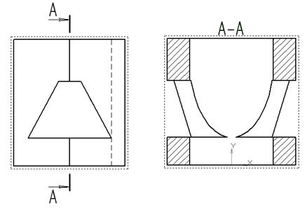
Fig. 113 Construction of a profile section
The direction of view and the text of the symbol can be selected on the command control panel at the bottom of the screen (Fig. 114). The construction of the cutting line is completed by clicking on the Create object button.
Fig. 114 Control panel for the command to construct sections and sections
4. On the Associative Views panel (Fig. 115), select the Cut Line button, then use the trap that appears on the screen to indicate the cut line. If everything is done correctly (the cut line must be drawn in the active form), then the cut line will turn red. After specifying the cut line A-A, a phantom image in the form of an overall rectangle will appear on the screen.
Fig. 115 Panel Associative Views
Using the Section/section switch on the Properties panel, you select the image type – Section (Fig. 116) and the scale of the displayed section.
Fig. 116 Control panel for the command to construct sections and sections
The profile section will be constructed automatically in projection connection and with standard designation. If necessary, projection communication can be turned off with a switch Projection connection (Fig. 116). To configure the parameters of the hatching that will be used in the created section (section), use the controls on the Hatching tab.

Fig. 117 Construction of a horizontal section B-B and section B-C
If the selected cutting plane when constructing a section coincides with the plane of symmetry of the part, then in accordance with the standard such a section is not designated. But if you simply erase the designation of a section, then due to the fact that the view and the section in the computer memory are interconnected, the entire section will be erased. Therefore, in order to delete a designation, you must first destroy the connection between the view and the section. To do this, click the left mouse button to select the section, and then click the right mouse button to bring up the context menu, from which select the Destroy View item (Fig. 97). The cut symbol can now be removed.
5. To construct a horizontal section, draw a cutting line B-B through the lower plane of the hole in the front view. You must first make the front view current by double-clicking the left mouse button. Then a horizontal section is constructed (Fig. 117).
6. When constructing a frontal section, combine part of the view and part of the section, because these are symmetrical figures. The outer edge of the prism is projected onto the line dividing the view and the section, so we will distinguish view and section with a solid thin wavy line drawn to the right of the axis of symmetry, because outer rib. To draw a wavy line, use the button Bezier curve located on the Geometry panel, drawn with the For break line style (Fig. 118). Sequentially specify the points through which the Bezier curve should pass. You can finish executing the command by clicking the Create object button.

Fig. 118 Selecting a line style for a break
Construction of sections
A section is an image of an object that is obtained by mentally dissecting the object with a plane. The section shows only what is located in the cutting plane.
The position of the cutting plane, with the help of which the section is formed, is indicated in the drawing by the section line, just as for cuts.
Sections, depending on their location in the drawings, are divided into extended and superimposed. The sections taken out are most often located on the free field of the drawing and are outlined with a main line. The superimposed sections are placed directly on the image of the object and outlined with thin lines (Fig. 119).


Fig. 119 Construction of sections
Let's consider the sequence of constructing a drawing of a prism with an offset inclined section B-B(Fig. 117).
1. Make a front view by active double-clicking the left mouse button on the view and draw a section line using the button Cut line . Select the text of the inscription В-В.
2. Using the Cut Line button located on the Associative Views panel (Fig. 115), the trap that appears will indicate the secant line plane B-B. Using the Section/section switch on the Property bar, select the image type – Section (Fig. 116), the scale of the displayed section is selected from the Scale window.
The constructed section is located in a projection link, which limits its movement in the drawing, but the projection link can be disabled using the button Projection communication.
On the finished drawing you should draw axial lines and, if necessary, add dimensions.
MINISTRY OF EDUCATION, SCIENCEAND YOUTH OF THE REPUBLIC OF CRIMEA
SMALL ACADEMY OF SCIENCES "SEEKER"
Department: mathematics
Section: mathematics
METHODS FOR CONSTRUCTING SECTIONS OF POLYHEDRONS
Work completed:
_______________
class student
Abstracts
Methods for constructing sections of polyhedra
Department: mathematics
Section: mathematics
Scientific supervisor:
The purpose of the study is study of various methods for constructing sections of polyhedra. For this andtheoretical material on this topic has been studied, methods for solving problems on constructing sections are systematized, examples of problems on the application of each method are given, examples of problems in the unified state exam on constructing sections and calculating their elements are considered.
INTRODUCTION……………………………………………………………………………….3
SECTION 1. CONSTRUCTION OF SECTIONS OF POLYHEDRONS BASED ON THE AXIOM SYSTEM OF SEREOMETRY……………………………………………………4
SECTION 2. TRACE METHOD IN CONSTRUCTING SECTIONS OF POLYHEDRONS………………………………………………………………………………10
SECTION 3. INTERNAL DESIGN METHOD
IN THE CONSTRUCTION OF SECTIONS OF POLYHEDES………………………14
SECTION 4. COMBINED METHOD FOR CONSTRUCTING SECTIONS
POLYhedra………………………………………………………17
SECTION 5. COORDINATE METHOD FOR CONSTRUCTING SECTIONS OF POLYHEDES……………………………………………………………………………….19
CONCLUSION……………………………………………………………25
REFERENCES……………………………………………………26
INTRODUCTION
Graduates will have to take an exam in mathematics, and knowledge and ability to solve stereometric problems is necessary in order, to write this exam onmaximum points. Relevance This work involves the need to independently prepare for the exam, and the topic under consideration is one of the most important.
A analysis of demo, diagnostic and training Unified State Exam options With 2009-2014 showed that 70% geometric tasks consist of tasks on constructing sections and calculating their elements– angles, areas.
IN curriculum tasks on constructing sections of polyhedra are assigned 2 academic hours, which is not enough to study this topic. At school, plane sections of polyhedra are constructed only on the basis of the axioms and theorems of stereometry. At the same time, there are other methods for constructing flat sections of polyhedra. The most effective are the trace method, the internal design method and the combined method. The coordinate method is very interesting and promising in terms of application to solving various problems. If the polyhedron is placed in a coordinate system and the cutting plane is specified by an equation, then constructing the section will be reduced to finding the coordinates of the points of intersection of the plane with the edges of the polyhedron.
Object of study: methods for constructing sections of polyhedra.
Purpose of the study: study various methods for constructing sections of polyhedra.
Research objectives:
1) Study theoretical material on this topic.
2) Systematize methods for solving problems on constructing sections.
3) Give examples of tasks for using each method.
4) Consider examples of problems in the Unified State Exam on constructing sections and calculating their elements.
SECTION 1
CONSTRUCTION OF SECTIONS OF POLYHEDRONS
BASED ON THE AXIOM SYSTEM OF SEREOMETRY
Definition. A section of a polyhedron by a plane is called geometric figure, which is the set of all points in space that simultaneously belong to a given polyhedron and plane; the plane is called a cutting plane.
The surface of a polyhedron consists of edges - segments and faces - flat polygons. Since a straight line and a plane intersect at a point, and two planes intersect along a straight line, then the section of a polyhedron by a plane is a plane polygon; the vertices of this polygon are the points of intersection of the cutting plane with the edges of the polyhedron, and the sides are the segments along which the cutting plane intersects its faces. This means that to construct the desired section of a given polyhedron with the plane α it is enough to construct the points of its intersection with the edges of the polyhedron. Then connect these points sequentially with segments.
The cutting plane α can be specified by: three points that do not lie on the same line; a straight line and a point not belonging to it; other conditions that determine its position relative to a given polyhedron. For example, in Fig. 1 a section of the quadrangular pyramid PABCD is constructed by the plane α, defined by the points M, K and H, belonging to the edges PC, PD and PB, respectively;
Fig.1
Task. In parallelepiped ABC DA 1 B 1 C 1 D 1 construct a section by plane, passing through the peaks C and D 1 and point K of the segment B 1 C 1 (Fig. 2, a).
Solution. 1. T. To . WITH ∈ DD 1 C 1, D 1 ∈ DD 1 C 1, then according to the axiom (through two points, belonging to the plane, passes through a straight line, and only one) let's construct a trace CD 1 in the plane DD 1 C 1 (Fig. 2, b).
2. Similarly in plane A 1 B 1 C 1 we will construct a trace DK, in the plane BB 1 C 1 we will construct a trace CK.
3. D 1 KC – the desired section (Fig..2, c)


a) b) c)
Fig.2
Task. Construct a section of the pyramid RABC with the plane α = (MKH), where M, K and H are the internal points of the edges RS, PB and AB, respectively (Fig. 3, a).
Solution. 1st step. Points M and K lie in each of the two planes α and RVS. Therefore, according to the axiom of intersection of two planes, the α plane intersects the RVS plane along the straight line MK. Consequently, the segment MK is one of the sides of the desired section (Fig. 3, b).
2nd step. Similarly, the segment KN is the other side of the desired section (Fig. 3, c).
3rd step. Points M and H do not lie simultaneously on any of the faces of the pyramid RABC, therefore the segment MH is not a side of the section of this pyramid. Straight lines KN and RA lie in the plane of the AVR face and intersect. Let's construct the point T= KH ∩AP (Fig. 3, d).
Since the straight line KN lies in the α plane, then the point T lies in the α plane. Now we see that the planes α and ARS have common points M and T. Consequently, according to the axiom of intersection of two planes, plane α and plane APC intersect along straight line MT, which, in turn, intersects edge AC at point R (Fig. 3, e).
4th step. Now, in the same way as in step 1, we establish that the plane α intersects the faces ACP and ABC along the segments MR and HR, respectively. Consequently, the required section is the quadrilateral MKHR (Fig. 3, f).
 Fig.3
Fig.3
Let's consider a more complex problem.
Task . Construct a section of the pentagonal pyramid PABCDE by plane
α = (KQR), where K, Q are the internal points of the edges RA and RS, respectively, and point R lies inside the face DPE (Fig. 4, a).
Solution . The lines QK and AC lie in the same plane ACP (according to the axiom of a straight line and a plane) and intersect at some point T 1 , (Fig. 4, b), while T 1 є α, since QК є α.
Straight line PR intersects DE at some point F (Fig. 4, c), which is the point of intersection of the plane ARR and side DE of the base of the pyramid. Then the lines KR and AF lie in the same plane ARR and intersect at some point T 2 (Fig. 4, d), while T 2 є α , as a point of the straight line KR є α (according to the axiom of the straight line and the plane).
Received: straight T 1 T 2 lies in the secant plane α and in the plane of the base of the pyramid (according to the axiom of the straight line and the plane), while the straight line intersects the sides DE and AE of the base ABCDE of the pyramid, respectively, at points M and N (Fig. 4, e), which are the points of intersection of the plane α with edges DE and AE of the pyramid and serve as the vertices of the desired section.
Further, the straight line MR lies in the plane of the face DPE and in the cutting plane α (according to the axiom of a straight line and a plane), while intersecting the edge PD at some point H - another vertex of the desired section (Fig. 4, f).
Next, let's build point T 3 - T 1 T 2 ∩ AB (Fig. 4, g), which, as a point of the straight line T 1 T 2 є α, lies in the plane a (according to the axiom of the line and the plane). Now the plane of the face RAB belongs to two points T 3 and To the cutting plane α, which means straight line T 3 K is the straight line of intersection of these planes. Straight T 3 K intersects edge PB at point L (Fig. 4, h), which serves as the next vertex of the desired section.
Thus, the “chain” of the sequence for constructing the desired section is as follows:
1. T 1 = QK∩ AC ; 2. F = PR ∩ DE;
3. T 2 = KR ∩ AF; 4. M = T 1 T 2 ∩ DE;
5.N= T 1 T 2 ∩ AE ; 6. N = MR ∩ PD;
7. T 3 = T 1 T 2 ∩ AB ; 8.L=T 3 K ∩ PB.
Hexagon MNKLQH is the required section.
Fig.4
A section of a polyhedron with parallel faces (prism, parallelepiped cube) can be constructed using the properties of parallel planes.
Task . Points M, P and R are located on the edges of the parallelepiped. Using the properties of parallel lines and planes, construct a section of this parallelepiped using the MPR plane.
Solution. Let points M, P and R be located on the edges of DD, respectively 1, BB 1 and SS 1 parallelepiped ABCBA 1 B 1 C 1 B 1 (Fig. 5, a).
Let us denote: (MPR) = α - cutting plane. We draw segments MR and PR (Fig. 5, b), along which the plane α intersects the faces CC, respectively 1 D 1 D and BB 1 C 1 From this parallelepiped. Segments MR and PR are the sides of the desired section. Next we use theorems on the intersection of two parallel planes with a third.
Since face AA is 1 B 1 B is parallel to face CC 1 D 1 D, then the straight line of intersection of the plane α with the plane of the face AA 1 in 1 B must be parallel to line MR. Therefore we draw the segment PQ || MR, Q є AB (Fig. 5, c); segment PQ is the next side of the desired section. Similarly, since face AA 1 D 1 D is parallel to face CC 1 in 1 B, then the straight line of intersection of the plane α with the plane of the face AA 1 D 1 D must be parallel to line PR. Therefore we draw the segment MH || PR, H = AD (Fig. 5, c); segment MN is another side of the desired section. On edges AB and AD of face ABCD, points Q є AB and H є AD were constructed, which are the vertices of the desired section. We draw the segment QH and get the pentagon MRPQH - the desired section of the parallelepiped.


a) b) c)
Rice. 5
SECTION 2
TRACE METHOD IN CONSTRUCTING SECTIONS OF POLYHEDRONS
Definition. The straight line along which the cutting plane α intersects the plane of the base of the polyhedron is called the trace of the plane α in the plane of this base.
From the definition of a trace we get: at each of its points straight lines intersect, one of which lies in the secant plane, the other in the plane of the base. It is this property of the trace that is used when constructing plane sections of polyhedra using the trace method. In this case, in the cutting plane it is convenient to use straight lines that intersect the edges of the polyhedron.
First, we define the secant plane by its trace in the plane of the base of the prism (pyramid) and by a point belonging to the surface of the prism (pyramid).
Task. Construct a cross section of the ABCVEA prism 1 B 1 C 1 D 1 E 1 plane α, which is given by the followingl in plane ABC of the base of the prism and point M belonging to edge DD 1 (Fig. 7, a).
Solution. Analysis. Let us assume that the pentagon MNPQR is the desired section (Fig. 6). To construct this flat pentagon, it is enough to construct its vertices N, P, Q, R (point M is given) - the points of intersection of the cutting plane α with the edges, respectively CC 1, BB 1, AA 1, EE 1 of this prism.

Rice. 6
To construct the point N = α ∩ СС 1 it is enough to construct the straight line of intersection of the cutting plane α with the plane of the face СDD 1 C 1 . To do this, in turn, it is enough to construct another point in the plane of this face, belonging to the cutting plane α. How to construct such a point?
Since it's straight l lies in the plane of the base of the prism, then it can intersect the plane of the face CDD 1 C 1 only at the point that belongs to the line CD = (CDD 1 ) ∩ (ABC), i.e. point X =l∩CD = l∩ (CDD 1 ) belongs to the cutting plane α. Thus, to construct the point N = α ∩ СС 1 it is enough to construct the point X =l ∩CD. Similarly, to construct points P = α ∩ BB 1, Q = α ∩ AA 1 and R = α ∩ EE 1 it is enough to construct the points accordingly: Y =l∩ BC, Z = l∩ AB and T = l∩ AE. From here
Construction.
X = l∩ CD (Fig. 7, b);
N = MX ∩ СС 1 (Fig. 7, b);
Y = l∩ BC (Fig. 7, c);
P = NY ∩ BB 1 (Fig. 7, c);
Z= l∩ AB (Fig. 7, c);
Q= PZ ∩ AA 1 (Fig. 7, d);
T= l∩ AE (Fig. 6);
R= QT ∩ EE 1 (Fig. 6).
Pentagon MNPQR is the required section (Fig. 6).
Proof . Since it's straight l is the trace of the cutting plane α, then the points X =l∩ CD, Y = l∩ BC, Z = l∩ AB and T= l ∩ AE belong to this plane.
Therefore we have:
М є α , X є α => МХ є α, then МХ ∩ СС 1 = N є α, which means N = α ∩ СС 1 ;
N є α, Y є α => NY є α, then NY ∩ ВВ 1 = Р є α, which means Р = α ∩ ВВ 1 ;
Р є α, Z є α => РZ є α, then PZ ∩ AA 1 = Q є α, which means Q = α ∩ AA 1 ;
Q є α, T є α => QТ є α, then QТ ∩ EE 1 =R є α, which means R = α ∩ Е 1 .
Therefore, MNPQR is the required section.


a) b)


c) d)
Rice. 7
Study. Track l cutting plane α does not intersect the base of the prism, and point M of the cutting plane belongs to the side edge DD 1 prisms. Therefore, the cutting plane α is not parallel to the side edges. Consequently, the points N, P, Q and R of intersection of this plane with the lateral edges of the prism (or extensions of these edges) always exist. And since, in addition, point M does not belong to the tracel , then the plane α defined by them is unique. This means that the problem has a unique solution.
Task. Construct a section of the pentagonal pyramid PABCDE with the plane given by the followingl and the internal point K of edge PE.
Solution. Schematically, the construction of the desired section can be depicted as follows (Fig. 8): T 1 → Q → T 2 → R → T 3 → M → T 4 → N.
Pentagon MNKQR is the required section.
The “chain” of the sequence of constructing the vertices of the section is as follows:
1. T 1 = l∩ AE; 2. Q = T 1 K ∩ RA;
3. T 2 = l∩ AB; 4. R = T 2 Q ∩ РВ;
5. T 3 = l∩ BC; 6. M = T 3 R ∩ RS;
7. T 4 = l∩CD; 8. N = T 4 M ∩ РD.

Rice. 8
The cutting plane is often defined by three points belonging to the polyhedron. In this case, to construct the desired section using the trace method, first construct a trace of the cutting plane in the plane of the base of the given polyhedron.
SECTION 3
INTERIOR DESIGN METHOD
IN THE CONSTRUCTION OF SECTIONS OF POLYHEDRONS
The internal design method is also called the correspondence method, or the method of diagonal sections.
When applying this method, each given point is projected onto the base plane. There are two possible types of design: central and parallel. Central projection is usually used when constructing sections of pyramids, with the top of the pyramid being the center of the projection. Parallel design is used when constructing sections of prisms.
Task . Construct a section of the pyramid PABCDE with the plane α = (MFR), if points M, F and R are internal points of the edges RA, RS and PE, respectively (Fig. 9, a).
Solution . Let us denote the plane of the base of the pyramid as β. To construct the required section, we construct the points of intersection of the cutting plane α with the edges of the pyramid.
Let's construct the point of intersection of the cutting plane with the edge PD of this pyramid.
Planes APD and CPE intersect plane β along straight lines AD and CE, respectively, which intersect at some point K (Fig. 9, c). The straight line PK = (APD) ∩ (CPE) intersects the straight line FR є α at some point K 1 : K 1 = RK ∩ FR (Fig. 9, d), while K 1 є α. Then: M є α, K 1 є α => straight line MK є a. Therefore point Q = MK 1 ∩ PD (Fig. 9, e) is the intersection point of the edge PD and the cutting plane: Q = α ∩ PD. Point Q is the vertex of the desired section. Similarly, we construct the point of intersection of the plane α and the edge РВ. Planes BPE and АD intersect plane β along straight lines BE and AD, respectively, which intersect at point H (Fig. 9, e). Straight line PH = (BPE) ∩ (APD) intersects straight line MQ at point H 1 (Fig. 9, g). Then straight line RN 1 intersects the edge PB at the point N = α ∩ PB - the vertex of the section (Fig. 9, h).
1. K = AD ∩ EC; 2. K 1 = RK ∩ RF;
3.Q= MK 1 ∩ R D; 4. H = BE ∩ A D;
5. Н 1 = РН ∩ МQ; 6. N = RН 1 ∩ РВ.
Pentagon MNFQR is the required section (Fig. 9, i).


a) b) c)


Where)


g) h) i)
Rice. 9
Task . Construct a cross section of the prism ABCDEA 1 B 1 C 1 D 1 E 1 , plane α, defined by points M є BB 1, P DD 1, Q EE 1 (Fig. 10).
Solution. Let us denote: β - the plane of the lower base of the prism. To construct the desired section, we construct the points of intersection of the plane α = (MPQ) with the edges of the prism.
Let us construct the point of intersection of the plane α with the edge AA 1 .
Planes A 1 AD and BEE 1 intersect the plane β along straight lines AD and BE, respectively, which intersect at some point K. Since the planes A 1 AD and BEE 1 pass through parallel edges AA 1 and BB 1 prisms and have a common point K, then straight line KK 1 their intersection passes through point K and is parallel to edge BB 1 . Let us denote the point of intersection of this line with the line QM: K 1 = KK 1 ∩ QM, KK 1 ║ BB 1 . Since QM є α, then K 1 є α.

Rice. 10
Received: Р є α, K 1 є α => straight RK 1 є α, while RK 1 ∩ AA 1 = R. Point R serves as the intersection point of plane α and edge AA 1 (R = α ∩ AA 1 ), therefore is the vertex of the desired section. Similarly, we construct the point N = α ∩ СС 1 .
Thus, the sequence of “steps” for constructing the desired section is as follows:
K = AD ∩ BE; 2. K 1 = KK 1 ∩ MQ, KK 1 || BB 1;
R = RK 1 ∩ AA 1 ; 4. H = EC ∩AD;
H 1 – HH 1 ∩ РR, НН 1 || CC 1; 6.N = QН 1 ∩ СС 1.
Pentagon MNPQR is the required section.
The entire history of geometry and some other branches of mathematics is closely connected with the development of the theory of geometric constructions. The most important axioms of geometry, formed by Euclid around 300 BC, clearly show the role that geometric constructions played in the formation of geometry.
There are special topics in school geometry that you look forward to, anticipating meeting incredibly beautiful material. Such topics include “Polyhedra and the construction of their sections.” Here not only opens amazing world geometric bodies with unique properties, but also interesting scientific hypotheses. And then the geometry lesson becomes a kind of research unexpected sides a familiar school subject.
In geometry lessons this year we covered the topic “Constructing sections of polyhedra.” As part of the program, we studied one method for constructing sections, but I became interested in what other methods exist.
The purpose of my work: Learn all the methods for constructing sections of polyhedra.
No geometric bodies have such perfection and beauty as polyhedra. “There are a shockingly small number of polyhedra,” L. Carroll once wrote, “but this very modest in number detachment managed to get into the very depths of various sciences.”
Currently, the theory of geometric constructions represents a vast and deeply developed area of mathematics associated with the solution of various fundamental issues that go into other branches of mathematics.
History of descriptive geometry
Even in ancient times, people drew and painted on rocks, stones, walls and objects household items images of things, trees, animals and people. He did this to satisfy his needs, including aesthetic ones. Moreover, the main requirement for such images was that the image evoke a correct visual idea of the shape of the depicted object.
With the growth of practical and technical applications of images (in the construction of buildings and other civil and military structures, etc.), requirements began to be placed on them so that the image could be used to judge the geometric properties, dimensions and relative positions of individual elements of a certain object. Such requirements can be judged by many ancient monuments that have survived to this day. However, strict geometrically based rules and image methods spatial figures(with respect to perspective) began to be systematically developed by artists, architects and sculptors only in the Renaissance: Leonardo da Vinci, Dürer, Raphael, Michelangelo, Titian and others.
Descriptive geometry as a science was created at the end of the 18th century by the great French geometer and engineer Gaspard Monge (1746 – 1818). In 1637, the French geometer and philosopher Rene Descartes (1596 - 1650) created the coordinate method and laid the foundations of analytical geometry, and his compatriot, engineer and mathematician Girard Desages (1593 - 1662), used this coordinate method to construct perspective projections and substantiated the theory axonometric projections.
In the 17th century, technical drawings, made in the form of plans and profiles to scale, successfully developed in Russia. Here, first of all, we should mention the drawings of the outstanding Russian mechanic and inventor I.P. Kulibin (1735 – 1818). His design for a wooden arched bridge made the first use of orthogonal projections (1773). (Orthogonal projection of a plane onto a line lying in it or a space onto a plane is a special case of parallel projection, in which the direction of the projection is perpendicular to the line or plane on which it is projected.)
A major contribution to the development of orthogonal projections was made by the French engineer A. Frezier (1682–1773), who was the first to consider projecting an object onto two planes - horizontal and frontal.
The greatest merit of G. Monge was the generalization of all scientific works his predecessors, the entire theory of methods for depicting spatial figures and the creation of a unified mathematical science of orthogonal projection - descriptive geometry.
The birth of this new science almost coincided with the foundation in St. Petersburg of Russia's first higher transport educational institution– Institute of the Corps of Railway Engineers (December 2, 1809)
Graduates of this institute, its professors and scientists made a significant contribution to the development of geometric methods of representation, to the theory and practice of descriptive geometry.
Definitions of polyhedra
In stereometry, figures in space are studied, called bodies . Visually, a (geometric) body must be imagined as a part of space occupied by a physical body and limited by a surface.
Polyhedron - this is a body whose surface consists of several flat polygons. The polyhedron is called convex , if it is located on one side of the plane of each planar polygon on its surface. General part such a plane and the surface of a convex polyhedron is called edge . The faces of a convex polyhedron are flat convex polygons. The sides of the faces are callededges of the polyhedron, and the vertices are vertices of the polyhedron.
Section of a polyhedron, a plane is a geometric figure that is the set of all points in space that simultaneously belong to a given polyhedron and plane; the plane is called a cutting plane.
The surface of a polyhedron consists of edges, segments and faces of flat polygons. Since a straight line and a plane intersect at a point, and two planes intersect along a straight line, then the section of a polyhedron by a plane isplanar polygon; the vertices of this polygon are the points of intersection of the cutting plane with the edges of the polyhedron, and the sides are the segments along which the cutting plane intersects its faces. This means that to construct the desired section of a given polyhedron with a plane α, it is enough to construct the points of its intersection with the edges of the polyhedron. Then connect these points sequentially with segments, while highlighting with solid lines the visible and dashed invisible sides of the resulting polygon section.
III. Methods for constructing sections of polyhedra
The method of sections of polyhedra in stereometry is used in construction problems. It is based on the ability to construct a section of a polyhedron and determine the type of section.
This material is characterized by the following features:
- The method of sections is used only for polyhedra, since various complex (oblique) types of sections of bodies of revolution are not included in the secondary school curriculum.
- The problems mainly use the simplest polyhedra.
- The problems are presented mainly without numerical data in order to create the possibility of their multiple use.
To solve the problem of constructing a section of a polyhedron, a student must know:
- What does it mean to construct a section of a polyhedron with a plane;
- How can a polyhedron and a plane be positioned relative to each other?
- How the plane is defined;
- When the problem of constructing a section of a polyhedron by a plane is considered solved.
Because the plane is defined:
- Three points;
- Straight and dot;
- Two parallel lines;
- Two intersecting lines
The construction of the section plane depends on the specification of this plane. Therefore, all methods for constructing sections of polyhedra can be divided into methods.
3.1 Construction of sections of polyhedra based on the system of stereometry axioms
Problem 1 . Construct a section of the pyramid RABC with the plane α = (MKH), where M, K and H are the internal points of the edges RS, PB and AB, respectively (Fig. 1, a).
Solution .
1st step . Points M and K lie in each of the two planes α and RVS. Therefore, according to the axiom of intersection of two planes, the α plane intersects the RVS plane along the straight line MK. Consequently, the segment MK is one of the sides of the desired section (Fig. 1, b).
2nd step . Similarly, the segment KN is the other side of the desired section (Fig. 1, c).
3rd step . Points M and H do not lie simultaneously on any of the faces of the pyramid RABC, therefore the segment MH is not a side of the section of this pyramid. Straight lines KN and RA lie in the plane of the AVR face and intersect. Let's construct the point T= KH ∩AP (Fig. 1, d).
Since the straight line KN lies in the α plane, then the point T lies in the α plane. Now we see that planes α and APC have common points M and T. Consequently, according to the axiom of intersection of two planes, plane α and plane APC intersect along straight line MT, which, in turn, intersects edge AC at point R (Fig. 1, d).
4th step . Now, in the same way as in step 1, we establish that the plane α intersects the faces ACP and ABC along the segments MR and HR, respectively. Consequently, the required section is the quadrilateral MKHR (Fig. 1, f).
Rice. 2
Task 2. Construct a section of the pyramid MABCD with the plane α = (CN), where K, H and P are the internal points of the edges MA, MV and MD, respectively (Fig. 2, a).
Solution. The first two steps are similar to steps 1 and 2 of the previous problem. As a result, we obtain the sides KR and KN (Fig. 2, b) of the desired section. Let's construct the remaining vertices and sides of the polygon - sections.
3rd step . Let us continue the segment KR until it intersects with the straight line AD at point F (Fig. 2, c). Since the straight line KR lies in the cutting plane α, the point F= KR ∩ AD = KR ∩ (ABC) is common to the planes α and ABC.
4th step . Let us continue the segment KH until it intersects with straight line AB at point L (Fig. 2, d). Since the straight line КН lies in the cutting plane α, the point L = КН ∩ АВ = КН ∩ (АВС) is common for the planes α and АВС.
Thus , points F and L are common to the planes α and ABC. This means that plane α intersects plane ABC of the base of the pyramid along straight line FL.
5th step . Let's draw a straight line FL. This straight line intersects the edges BC and DC, respectively, at points R and T (Fig. 2, e), which serve as the vertices of the desired section. This means that plane α intersects the face of the base ABCD along the segment RT - the side of the desired section.
6th step . Now we draw segments RH and PT (Fig. 2, f), along which the plane α intersects the faces of the IUD and MCD of this pyramid. We obtain the pentagon PKHRT - the desired section of the MABCD pyramid (Fig. 2, f).
Let's consider a more complex problem.
Problem 3 . Construct a section of the pentagonal pyramid PABCDE with the plane α = (KQR), where K, Q are the internal points of the edges RA and RS, respectively, and point R lies inside the face DPE (Fig. 3, a).
Solution . The straight lines (QK and AC lie in the same plane ACP (according to the axiom of a straight line and a plane) and intersect at some point T1, (Fig. 3 b), while T1 є α, since QK є α.
Straight line PR intersects DE at some point F (Fig. 3, c), which is the point of intersection of the plane ARR and side DE of the base of the pyramid. Then the straight lines KR and AF lie in the same plane APR and intersect at some point T2 (Fig. 3, d), while T2 є α, as a point of the straight line KR є α (according to the axiom of the straight line and the plane).
Received: straight line T1 T2 lies in the secant plane α and in the plane of the base of the pyramid (according to the axiom of straight line and plane), while the straight line intersects the sides DE and AE of the base ABCDE of the pyramid, respectively, at points M and N (Fig. 3, e), which are the intersection points plane α with edges DE and AE of the pyramid and serve as the vertices of the desired section.
Next , the straight line MR lies in the plane of the face DPE and in the cutting plane α (according to the axiom of a straight line and a plane), while intersecting the edge PD at some point H - another vertex of the desired section (Fig. 3, f).
Next, Let's construct a point T3 - T1T2 ∩ AB (Fig. 3, g), which, as a point of the straight line T1T2 є α, lies in the plane a (according to the axiom of the straight line and the plane). Now the plane of the face RAB belongs to two points T3 and to the cutting plane α, which means that the straight line T3K is the straight line of intersection of these planes. Straight line Т3К intersects edge РВ at point L (Fig. 3, h), which serves as the next vertex of the desired section.
Rice. 3
Thus, the “chain” of the sequence for constructing the desired section is as follows:
1. T1 = QK ∩AC;
2. F = PR ∩ DE;
3. T2 = KR ∩ AF;
4. М = Т1Т2 ∩ DE;
5. N = T1T2 ∩ AE;
6. Н = MR ∩ PD;
7. T3 = T1T2 ∩ AB;
8. L = T3K ∩ PB.
Hexagon MNKLQH is the required section.
Section of the pyramid in Fig. 1 and the section of the cube in Fig. 2 are constructed based only on the axioms of stereometry.
At the same time, a section of a polyhedron with parallel faces (prism, parallelepiped, cube) can be constructed using the properties of parallel planes.
3.2 The trace method in constructing plane sections of polyhedra
The straight line along which the cutting plane α intersects the plane of the base of the polyhedron is called the trace of the plane α in the plane of this base.
From the definition of a trace we get: at each of its points straight lines intersect, one of which lies in the secant plane, the other in the plane of the base. It is this property of the trace that is used when constructing plane sections of polyhedra using the trace method. Moreover, in the secant plane, it is convenient to use straight lines that intersect the edges of the polyhedron.
First, we define the secant plane by its trace in the plane of the base of the prism (pyramid) and by a point belonging to the surface of the prism (pyramid).
Problem 1 . Construct a section of the prism АВСВЭА1В1С1D1Э1 by the plane α, which is specified by the trace l in the plane ABC of the base of the prism and by the point M belonging to the edge DD1.
Solution. Analysis . Let us assume that the pentagon MNPQR is the desired section (Fig. 4). To construct this flat pentagon, it is enough to construct its vertices N, P, Q, R (point M is given) - the intersection points of the cutting plane α with the edges CC1, BB1, AA1, EE1 of the given prism, respectively.
E1 D1
To construct the point N =α ∩ CC1, it is enough to construct the straight line of intersection of the cutting plane α with the plane of the face СDD1C1. To do this, in turn, it is enough to construct another point in the plane of this face, belonging to the cutting plane α. How to construct such a point?
Since the straight line l lies in the plane of the base of the prism, it can intersect the plane of the face СDD1C1 only at a point that belongs to the straight line CD = (CDD1) ∩ (АВС), i.e. the point X = l ∩ СD = l ∩ (CDD1) belongs to the cutting plane α. Thus, to construct the point N = α ∩ CC1, it is sufficient to construct the point X = l ∩ CD.
Similarly, to construct the points P = α ∩ BB1, Q = α ∩ AA1 and R = α ∩ EE1, it is sufficient to construct the points respectively: Y = l ∩ BC, Z = 1 ∩ AB and T =1 ∩ AE.
Construction. We build (Fig. 5):
1. X = l ∩ CD (Fig. 5, b);
2. N = MX ∩ CC1 (Fig. 5, c);
3. У = l ∩ ВС (Fig. 5, d);
4. P = NY ∩ BB1 (Fig. 5, e);
5. Z = 1 ∩ AB (Fig. 5, f);
6. Q= PZ ∩ AA1 (Fig. 5, g);
7. T= l ∩ AE (Fig. 5, h);
8. R= QT ∩ EE1 (Fig. 5, i).
Pentagon MNPQR is the required section (Fig. 5, j).
Proof. Since the line l is the trace of the cutting plane α, then the points X = l ∩ CD, Y = l ∩ BC, Z = 1 ∩ AB and T= l ∩ AE belong to this plane.
Therefore we have:
М Є α, X Є α => МХ є α, then МХ ∩ СС1 = N є α, which means N = α ∩ СС1;
N Є α, Y Є α => NY Є α, then NY ∩ BB1= P Є α, which means P = α ∩ BB1;
Р Є α, Z Є α => РZ Є α, then PZ ∩ AA1 = Q Є α, which means Q = α ∩ AA1;
Q Є α, T Є α => QТ Є α, then QТ ∩ EE1 =R Є α, which means R = α ∩ EE1.
Therefore, MNPQR is the required section.
Study. The trace l of the cutting plane α does not intersect the base of the prism, and the point M of the cutting plane belongs to the side edge DD1 of the prism. Therefore, the cutting plane α is not parallel to the side edges. Consequently, the points N, P, Q and R of intersection of this plane with the lateral edges of the prism (or extensions of these edges) always exist. And since, in addition, the point M does not belong to the trace l, then the plane α defined by them is unique. This means that the problem (always) has a unique solution.
3.3 Internal design method for constructing plane sections of polyhedra
In some textbooks, the method of constructing sections of polyhedra, which we will now consider, is called the method of internal projection or the method of correspondences, or the method of diagonal sections.
Problem 1 . Construct a section of the pyramid PABCDE with the plane α = (MFR), if points M, F and R are internal points of the edges RA, RS and PE, respectively. (Fig. 6)
Solution . Let us denote the plane of the base of the pyramid as β. To construct the desired section, we will construct the points of intersection of the cutting plane α with the edges of the pyramid.
Let's construct the point of intersection of the cutting plane with the edge PD of this pyramid.
The planes APD and CPE intersect the plane β along straight lines AD and CE, respectively, which intersect at some point K. The straight line PK = (APD) ∩ (CPE) intersects the straight line FR є α at some point K1: K1 = PK ∩ FR, with this K1 є α. Then: M є α, K1 є α => straight line MK є a. Therefore, the point Q = MK1 ∩ PD is the intersection point of the edge PD and the cutting plane: Q =α ∩ PD. Point Q is the vertex of the desired section. Similarly, we construct the intersection point of the plane α and the edge PB. Planes BPE and АD intersect plane β along straight lines BE and AD, respectively, which intersect at point H. Straight РН = (ВРЭ) ∩ (АРD) intersects straight line МQ at point Н1. Then straight line RN1 intersects edge РВ at point N = α ∩ РВ - the top of the section.
Thus , the sequence of steps for constructing the desired section is as follows:
1. K = AD ∩ EC; 2. К1 = РК ∩ RF;
3. Q = MK1 ∩ РD; 4. H = BE ∩ AD;
5. Н1 = РН ∩ МQ; 6. N = RН1 ∩ РВ.
Pentagon MNFQR is the required section.
3.4 Combined method in constructing plane sections of polyhedra
The essence of the combined method for constructing sections of polyhedra is as follows. At some stages of constructing a section, either the trace method or the internal design method is used, and at other stages of constructing the same section, the studied theorems on parallelism, perpendicularity of lines and planes are used.
To illustrate the application of this method, consider the following problem.
Task 1.
Construct a section of the parallelepiped ABCDA1B1C1D1 by plane α, defined by points P, Q and R, if point P lies on the diagonal A1C1, point Q on edge BB1 and point R on edge DD1. (Fig. 7)
Solution
Let's solve this problem using the trace method and theorems on the parallelism of lines and planes.
First of all, let's construct the trace of the cutting plane α = (РQR) on the ABC plane. To do this, we construct points Т1 = РQ ∩ Р1В (where PP1 ║AA1,P1є AC) and T2 = RQ ∩ ВD. Having constructed the trace T1T2, we notice that point P lies in the plane A1B1C1, which is parallel to the plane ABC. This means that plane α intersects plane A1B1C1 along a straight line passing through point P and parallel to straight line T1T2. Let's draw this line and denote by M and E the points of its intersection with the edges A1B1 and A1D1, respectively. We get: M = α ∩ A1B1, E = α∩ A1D1. Then the segments ER and QM are the sides of the desired section.
Further, since the plane BCC1 is parallel to the plane of the face ADD1A1, then the plane α intersects the face BCC1B1 along the segment QF (F= α ∩ CC1), parallel to the straight line ER. Thus, the pentagon ERFQM is the required section. (Point F can be obtained by performing RF║ MQ)
Let's solve this problem using the internal projection method and theorems on the parallelism of lines and planes.(Fig. 8)
Rice. 8
Let H=AC ∩ BD. Drawing straight line НН1 parallel to edge ВВ1 (Н1 є RQ), we construct point F: F=РН1 ∩ CC1. Point F is the point of intersection of plane α with edge CC1, since РН1 є α. Then the segments RF and QF along which the plane α intersects the faces CC1D1D and ВСС1В1 of this parallelepiped, respectively, are the sides of its desired section.
Since the plane ABB1 is parallel to the plane CDD1, the intersection of the plane α and the face ABB1A1 is the segment QM (M Є A1B1), parallel to the segment FR; segment QM - side of the section. Further, the point E = MP ∩ A1D1 is the intersection point of the plane α and the edge A1D1, since MP є α. Therefore, point E is another vertex of the desired section. Thus, the pentagon ERFQM is the required section. (Point E can be constructed by drawing the straight line RE ║ FQ. Then M = PE ∩ A1B1).
IV. Conclusion
Thanks to this work, I summarized and systematized the knowledge gained during this year’s geometry course, became familiar with the rules for performing creative work, gained new knowledge and applied it in practice.
I would like to put my new acquired knowledge into practice more often.
Unfortunately, I did not consider all methods for constructing sections of polyhedra. There are many more special cases:
- constructing a section of a polyhedron with a plane passing through given point parallel to a given plane;
- constructing a section passing through a given line parallel to another given line;
- constructing a section passing through a given point parallel to two given intersecting lines;
- constructing a section of a polyhedron with a plane passing through a given line perpendicular to a given plane;
- constructing a section of a polyhedron with a plane passing through a given point perpendicular to a given line, etc.
In the future, I plan to expand my research and supplement my work with an analysis of the above-listed special cases.
I believe that my work is relevant, since it can be used by middle and high school students for independent preparation for the Unified State Exam in mathematics, for in-depth study of material in electives, and for self-education of young teachers. High school graduates must not only master the material school programs, but also be able to apply it creatively and find a solution to any problem.
V. Literature
- Potoskuev E.V., Zvavich L.I. Geometry. 10th grade: Textbook for general education institutions with in-depth and specialized study of mathematics. - M.: Bustard, 2008.
- Potoskuev E.V., Zvavich L.I. Geometry. 10th grade: Problem book for general education institutions with in-depth and specialized study of mathematics. - M.: Bustard, 2008.
- Potoskuev E.V. Image of spatial figures on a plane. Construction of sections of polyhedra. Tutorial for students of the Faculty of Physics and Mathematics of a Pedagogical University. - Tolyatti: TSU, 2004.
- Scientific and practical magazine for high school students “Mathematics for Schoolchildren”, 2009, No. 2/No. 3, 1-64.
- Geometry in tables - Textbook for high school students - Nelin E.P.
- Geometry, grades 7-11, Reference materials, Bezrukova G.K., Litvinenko V.N., 2008.
- Mathematics, Reference Guide, For high school students and those entering universities, Ryvkin A.A., Ryvkin A.Z., 2003.
- Algebra and geometry in tables and diagrams, Roganin A.N., Dergachev V.A., 2006.
Do you know what is called the section of polyhedra by a plane? If you still doubt the correctness of your answer to this question, you can check yourself quite simply. We suggest you take a short test below.
Question. What is the number of the figure that shows the section of a parallelepiped by a plane?
So, the correct answer is in Figure 3.
If you answer correctly, it confirms that you understand what you are dealing with. But, unfortunately, even the correct answer to a test question does not guarantee you the highest grades in lessons on the topic “Sections of polyhedra.” After all, the most difficult thing is not recognizing sections in finished drawings, although this is also very important, but their construction.
To begin with, let us formulate the definition of a section of a polyhedron. So, a section of a polyhedron is a polygon whose vertices lie on the edges of the polyhedron, and whose sides lie on its faces.
Now let’s practice quickly and accurately constructing intersection points ![]() a given straight line with a given plane. To do this, let's solve the following problem.
a given straight line with a given plane. To do this, let's solve the following problem.
Construct the intersection points of straight line MN with the planes of the lower and upper bases of the triangular prism ABCA 1 B 1 C 1, provided that point M belongs to the side edge CC 1, and point N belongs to edge BB 1.
Let's start by extending straight line MN in both directions in the drawing (Fig. 1). Then, in order to obtain the intersection points required by the problem, we extend the lines lying in the upper and lower bases. And now comes the most difficult moment in solving the problem: which lines in both bases need to be extended, since each of them has three lines.
In order to correctly complete the final step of construction, it is necessary to determine which of the direct bases are in the same plane as the straight line MN of interest to us. In our case, this is straight CB in the lower and C 1 B 1 in the upper bases. And it is precisely these that we extend until they intersect with the straight line NM (Fig. 2).

The resulting points P and P 1 are the points of intersection of the straight line MN with the planes of the upper and lower bases of the triangular prism ABCA 1 B 1 C 1 .
After analyzing the presented problem, you can proceed directly to constructing sections of polyhedra. The key point There will be reasoning here that will help you arrive at the desired result. As a result, we will eventually try to create a template that will reflect the sequence of actions when solving problems of this type.
So, let's consider the following problem. Construct a section of a triangular prism ABCA 1 B 1 C 1 with a plane passing through points X, Y, Z belonging to edges AA 1, AC and BB 1, respectively.
Solution: Let's draw a drawing and determine which pairs of points lie in the same plane.
 Pairs of points X and Y, X and Z can be connected, because they lie in the same plane.
Let's construct an additional point that will lie on the same face as point Z. To do this, we will extend the lines XY and CC 1, because they lie in the plane of the face AA 1 C 1 C. Let's call the resulting point P.
Points P and Z lie in the same plane - in the plane of the face CC 1 B 1 B. Therefore, we can connect them. The straight line PZ intersects the edge CB at a certain point, let's call it T. Points Y and T lie in the lower plane of the prism, connect them. Thus, the quadrilateral YXZT was formed, and this is the desired section. 
Let's summarize. To construct a section of a polyhedron with a plane, you must:
1) draw straight lines through pairs of points lying in the same plane.
2) find the lines along which the section planes and faces of the polyhedron intersect. To do this, you need to find the intersection points of a straight line belonging to the section plane with a straight line lying in one of the faces.
The process of constructing sections of polyhedra is complicated because it is different in each specific case. And no theory describes it from beginning to end. In fact, there is only one sure way to learn how to quickly and accurately construct sections of any polyhedra - this is constant practice. The more sections you build, the easier it will be for you to do this in the future.
website, when copying material in full or in part, a link to the source is required.
We also recommend
 Temple of the Tikhvin Icon of the Mother of God on Ave.
 The miraculous icon of St. Nicholas of Zaraisk St. Nicholas of Zaraisk with life
 How to smoke cheek meat at home
 Receiving a property deduction through an employer
 Interpretation of sleep to treat in dream books
 Buckwheat in a frying pan with onions and carrots Cook buckwheat with carrots and onions