Reworking the brake system. (Detailed manual, many photos)
Even in a modern car, there is a possibility that the brake system will fail at any moment, especially in a situation where there was no timely maintenance of the car and this system in particular. Therefore, constant diagnostics and thorough repairs are an opportunity to protect yourself and your passengers. Often, brake system repair involves replacing brake pads or brake discs. But, in addition to this, the brake bleeding procedure is performed, which is not difficult to do with your own hands.
Therefore, today we will talk in detail about how to bleed the brakes on a VAZ 2101 car with your own hands. There are no particular problems with this, but you need to remember some features.
When, while driving, it is noticed that the wheels do not engage at the same time or there is a strong dip in the pedal, then this indicates the presence of air inside the system. The presence of air bubbles in the system significantly reduces the effectiveness of the brakes, which can negatively affect the safety of the driver and passengers.
The process of bleeding the brakes on the VAZ 2101 is precisely used to remove air from the system. Work begins with the furthest wheel, ending with the one closest to the GTZ. First you need to work on the rear right wheel.
Before you start lifting the car, you should prevent problems from arising. To do this, you need to use the wheel chocks and engage second gear. When work is carried out in a pit, then there is no need to use a jack.
Reasons for air getting into the brake system:
- Air gets in during a complete brake fluid change.
- Air may enter when replacing one of the brake system components, for example, when replacing the master cylinder.
- Air can also enter the system due to damaged brake hoses.
- Depressurization of the main brake cylinder.
Note! The brake fluid will gradually be replenished with water from the condensate, and its cloudiness will become a signal of this. Accordingly, brake fluid must be replaced every 45 thousand mileage.
HOW TO BLEED THE BRAKE SYSTEM OF A VAZ 2110 WITH YOUR OWN HANDS
To bleed the brake system, use the following tools:- Container for draining old fluid.
- Special key for "8" or "10".
- Brake fluid in the required volume.
- A small piece of rubber hose.
- A lift or inspection hole for ease of use.
- Additionally, a second person is needed. Sometimes an additional option is used when there is no assistant. But, this method is exclusively for experienced car enthusiasts.
Note! When the rear wheels have been suspended, then you first need to unlock the rear brake pressure regulator. In this situation, you need to move the "sorcerer".
It was said above that you should start the process of bleeding the brakes from the rear right wheel. After it you need to work with the rear left, the front left and the last one is the front right.
1. You need to start by opening the hood and unscrewing the cap of the brake fluid reservoir.
2. If the level is minimal, then the liquid must be added to the maximum level “MAX”. Additionally, you need to conduct a full check of the tightness of connections and hoses, because if they are damaged, there is no point in bleeding the system.
3. The cap of the rear right wheel bleeding fitting must be carefully removed, after which one end of the rubber pipe is put on it, and the other end is lowered into a previously prepared container.
4. The assistant must get behind the wheel and begin the pumping process. He should pump the brake pedal in cycles of 7-8 times, and at the end of all cycles the pedal is pressed and firmly fixed in a fully depressed state.
5. The main task is to loosen the fitting by approximately half a turn; in addition, you will see how brake fluid with air bubbles oozes out. And the assistant must keep the pedal depressed all this time.
6. When the brake fluid with air has escaped into the container, then the fitting should be carefully tightened.
7. This procedure must be done several times until clean brake fluid without bubbles flows from the fitting. If necessary, then the brake fluid must be added to the reservoir to the maximum level.
8. When bleeding is completed, screw the fitting back and put the rubber cap on it.
9. All the above steps must be repeated for each wheel separately, after which pumping can be considered complete.
10. When, after bleeding, the pedal becomes too hard or soft, then you should carefully check the tightness of the brake lines and connections.
BRAKE OPERATION DIAGRAM
When the system is released and the brake pedal, under the action of spring 20, is pulled all the way to the brake light switch 19, the pusher 16 is pulled back together with the pedal. Pistons 10 and 13 of the main cylinder, under the action of return springs, are pressed to the rear extreme position until it stops limiting screws 12. In this position, the spacer bushings 14, resting against the screws 12, press the sealing rings 11 from the end of the piston groove and through the resulting gaps the working cavities of the cylinder communicate with the hydraulic cylinder reservoir and high-pressure pipelines. Thus, there is no pressure in the brake actuator. Therefore, the pistons 2, under the action of elastic deformation of the sealing rings 4, are retracted inside the cylinders and do not exert pressure on the brake pads of the front brakes, which will be in light contact with the surface of the brake disc. When the car moves without braking, that is, when there is no pressure in the hydraulic drive, the piston 41, under the action of the spring 43 and the torsion lever 42, is raised up until it stops at the plug 36. Therefore, the housing cavities located above and below the piston head communicate freely. This opens a free passage of fluid to the rear brake wheel cylinders. But since there is no pressure in the entire brake drive, the brake pads 28 are pressed away from the drums by tension springs. When braking, when the driver presses the brake pedal, the pusher 16 moves the piston 13. When the piston 13 moves, the spacer sleeve 14 moves away from the limit screw 12 and the sealing ring 11 is pressed by a spring to the end of the piston groove. Thus, the compensation gap is closed and the cavities of the cylinder and tank are separated. Therefore, with further movement of the piston 13 in the working area of the front brake drive, fluid pressure is created, which is transmitted through pipelines and hoses to the wheel cylinders of the front brakes. It also affects the floating piston 10, which, when moving, creates pressure in the rear brake drive. Under increasing fluid pressure in the working cavities, the front piston sealing rings expand and begin to fit more tightly to the surface of the cylinder and to the end of the grooves, improving the seal of the pistons in the cylinder. Under fluid pressure, pistons 2 and 31 of the wheel cylinders of the front and rear brakes extend, pressing the pads against the brake disc 8 and drum 35. The created braking torques slow down the rotation of the front and rear wheels. At the same time, the load is redistributed along the axles of the car: the load on the front axle increases, and on the rear axle it decreases. This leads to the raising of the rear of the body, that is, the distance between the beam rear axle and the body increases. At the same time, the short arm of the lever 42 is lowered, and the piston 41 of the pressure regulator begins to fall under fluid pressure, compressing the spring 43. At the moment of full braking, the maximum load moves from the rear axle to the front and the greatest lift of the body occurs. The grip of the wheels on the road deteriorates, the pressure of the torsion lever 42 on the piston 41 decreases. Due to the larger area of the end face of the piston head, the force from fluid pressure P2 lowers the piston down until the head comes into contact with seal 37. Further flow of fluid to the wheel cylinders of the rear brakes stops, that is, the braking torque on the rear wheels does not increase, despite pressing the brake pedal firmly and further increase in pressure P1. Therefore, the rear wheels do not lock and the car does not skid. When the brake pedal is released, it returns to its original position under the action of the return spring 20, dragging the pusher 16 with it. The pistons 10 and 13, under the force of the return springs, are pushed to their extreme position and rest against the limit screws 12. The spacers 14 move the sealing rings 11 away from the end of the grooves. , and through the resulting gap the working cavities of the master cylinder communicate with the cavities of the master cylinder tank. Pistons 2 of the front brake are retracted from the pads due to the elasticity of the sealing rings 4, and pistons 31 of the rear brake - by shortening the tension springs until they stop at the adjusting eccentrics. If the rear brake drive circuit fails due to its leakage, piston 10, under fluid pressure, moves all the way into the master cylinder plug, after which the pressure in the front brake drive circuit begins to increase. Due to the free movement of piston 10, the free play of the brake pedal increases and only the drive operates front brakes. If the front brake drive circuit fails, piston 13 moves forward until it stops against piston 10, after which the rear brake drive circuit begins to operate. The free play of the brake pedal also increases. It should be remembered that when increasing the free play of the brake pedal, it is not recommended to press the pedal repeatedly, as this will not speed up braking, but rather will lengthen the time the brakes operate. Continue to depress the pedal fully and, if necessary, apply the parking brake. If any brake drive circuit is damaged, the fluid level control lamp lights up, signaling a drop in the fluid level in the reservoir. The parking brake system acts on the brake mechanisms of the rear wheels through a mechanical drive. When the lever 25 (see Fig. 22) is moved up, after selecting the free play of the lever equal to 45 clicks, the front 38 and rear 37 drive cables are tensioned and the force is transferred to the levers 24 (see Fig. 21) of the manual drive of the pads. When turning the lever 24 on the finger 26; the force through the expansion bar 27 is first transmitted to the front brake shoe until it is completely pressed against the drum. After which the lever 24 moves relative to the point of contact with the expansion bar, and its upper arm presses the other block against the drum. In this case, the control lamp on the instrument cluster lights up with a red blinking light, since the stop 42 (see figure) of the lever moves away from the rod of the lamp switch and the circuit is closed.Fig.1
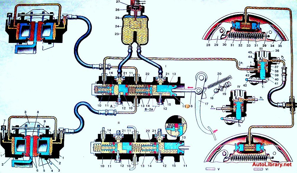
Fig.1 Brake operation diagram
1 . Front brake wheel cylinder; 2 3 . Front brake caliper; 4 . O-ring; 5 . Dust protection ring; 6 . Brake pads; 7 . Connection for bleeding brakes; 8 . Brake disc; 9 . Brake pad mounting pin; 10 . Rear brake drive piston; 11 . O-ring; 12 .Piston limit screw; 13 . Front brake drive piston; 14 . Spacer sleeve; 15 . Main cylinder; 16 . Pusher; 17 . Brake pedal; 18 . Stop light switch stop; 19 . Brake light switch. 20 . Pedal release spring; 21 . Union; 22 . Support cup; 23 . Master cylinder reservoir; 24 . Float; 25 . Pusher; 26 . Fixed contact; 27 . Movable contact; 28 . Rear brake pad; 29 . Parking brake lever; 30 . Pad stop; 31 . Wheel cylinder piston; 32 . Rear brake wheel cylinder; 33 . Piston spacer spring; 34 . Friction pad pad; 35 . Brake drum; 36 . Pressure regulator housing plug; 37 . Piston head seal; 38 . Spring plate; 39 . Spring support washer; 40 . Piston O-ring; 41 . Pressure regulator piston; 42 . Pressure regulator drive lever; 43 . Pressure regulator piston spring; 44 . Sleeve; 45 . Pressure regulator housing; I. Braking; II. Complete disinhibition; III. The pressure P1 in the master cylinder is equal to the pressure P2 in the wheel cylinders of the rear brakes; IV. Pressure P1 in the master cylinder is greater than pressure P2 in the wheel cylinders of the rear wheels; V. Free brake fluid; VI. High pressure brake fluid.
Visual daily monitoring, diagnostics and pumping brakes VAZ 2101, are the primary responsibility of the owner of such a car model to create safe driving conditions.
The need to pump the brakes of the VAZ 2101 is caused by problems with the brakes, which manifest themselves in the form of a delayed reaction to pressing the brake pedal, or such a reaction is sluggish and the car cannot sharply slow down. This behavior of the brakes indicates an early diagnostic measures and troubleshooting identified problems.
Brake repair methods
Brake repair may include:
- installation of pads with new coating;
- purchasing new brake discs;
- bleeding the entire brake system.
All of the above manipulations with brakes, with minimal skills, can be performed independently, both in the garage and on the street. The main thing is to have a set of necessary tools and desire.
Before you start pumping a VAZ 2101, you need to make sure that such a procedure is advisable. The essence of the operation itself is to squeeze out air bubbles from the system. The presence of such air gaps is determined at the moment of braking. When the brake pedal is pressed, it may fall all the way to the floor, or the wheels do not brake synchronously, and this will indicate that the fluid does not reach the brakes at the same time.
Bleeding procedure
Pumping begins with the wheel that has the greatest distance from the cylinder with brake fluid. As a rule, on a VAZ 2101 this is right wheel under the rear trunk. This is where you need to jack up the car..
Before this, in order to protect yourself as much as possible from possible movements of the car hanging on the jack, you need to put something under the remaining tires. It is best if these are special anti-recoil “shoes”, but bricks will also work. After this the lever checkpoint is set to the 2nd speed position and you can start jacking up the car.
The procedures listed above can be omitted, with the exception of laying bricks when pumping is carried out on an overpass or inspection pit.
 Reasons There are several formations of air gaps in hoses:
- the replacement of the main cylinder was carried out carelessly, without following the technology for repairing brake systems;
- when adding or replacing fluid in the system;
- due to loss of tightness of the system, which was the result of cracks in the pipes or connecting places that were not detected during vehicle inspections.
When using a car for a long time without necessarily changing the fluid in the braking system, it loses its performance characteristics, becomes black, and “pulls” water from the condensate. To ensure that the quality of the brake mixture does not affect the efficiency and safety of movement, it is necessary ensure that it is replaced regularly:
- or once every three years;
- or every 40 thousand km.
Step-by-step pumping algorithm
Required tools and additional equipment:
- The key is “10”;
- (if necessary, see above);
- New brake mixture (help article " ");
- Tube from a medical blood transfusion system;
- A basin or other container for draining the waste, at least 10 liters;
- Assistant.
- Subsequence wheels when “bleeding” - rear right, front left, rear left and front right.
Working brake system VAZ-2101
Working brake system VAZ-2101
Brake system diagram
1 – front brake protective housing;
2, 18 – pipelines connecting two cylinders of the front brake caliper;
3 – caliper;
4 – hydraulic drive reservoir;
5 – brake light switch;
6 – parking brake lever;
7 – adjusting eccentrics of the right rear brake;
8 – fitting for bleeding the hydraulic drive of the rear brakes;
9 – pressure regulator;
10 – stop signal;
11 – rear brake wheel cylinder;
12 – lever for manual drive of the pads and expansion bar;
13 – adjusting eccentric of the left rear brake;
14 – brake pad;
15 – rear cable guide;
16 – guide roller;
17 – brake pedal;
19 – fitting for bleeding the hydraulic drive of the front brakes;
20 – brake disc;
21 – main cylinder.
This brake system has two circuits that provide independent drive to the front and rear wheel brakes. Both circuits are driven by one pedal 17 (see Fig. Diagram of the brake system), which is attached together with the clutch pedal to the front panel of the body using a bracket.
In addition to the brake pedal, the hydraulic drive includes the main brake cylinder 21, the main cylinder reservoir 4, the rear brake pressure regulator 9, the brake mechanisms of the front and rear wheels along with the working cylinders and pipelines.
Master brake cylinder
The brake master cylinder is attached to the clutch and brake pedal bracket. Pistons 3 and 5 (see Fig. Main cylinder of the hydraulic brake drive) drive different circuits. Both pistons take their original position under the action of springs 8, which press the pistons until they stop against the screws 7. The tightness of the pistons in the cylinder is ensured by four o-rings 6. The housing is closed at the front
plug 1.
Pedal assembly
Pedals 6 (see Fig. Parts of the clutch and brake pedal bracket) and 19 are suspended on bracket 1 using an axis made in the form of a bolt.
Axle 18 is secured with nut 2 in the holes of the bracket cheeks. The internal bushings 4 and 14 of the clutch and brake pedals are clamped on the axis between the cheeks of the bracket and the spacer bushing 7. Pedals are pivotally mounted on these bushings, in the hubs of which outer bushings 5 and 9 are pressed. Pushers 20 are pivotally attached to both pedals, acting on the pistons of the hydraulic cylinders. The reverse travel of the clutch pedal is limited by a buffer 11 installed on the head of the bolt 12. The master cylinders of the clutch release drive and the brake drive are attached to the bracket shelf.
Pressure regulator
A pressure regulator 9 (see Fig. Brake system diagram) is connected to the rear brake drive circuit, which adjusts the pressure in the rear brake drive depending on the position of the body relative to the rear axle beam, i.e. depending on the vehicle load. It acts as a restriction valve that automatically cuts off the flow of brake fluid to the rear brakes, reducing the likelihood of rear wheel skidding when braking.
The regulator is mounted on the body bracket and connected to the rear axle beam through torsion lever 12 (see Fig. Parts of the pressure regulator drive) and rod 7. The other end of the torsion lever acts on piston 10 (see Fig. Rear brake pressure regulator in non-working position) .
Fluid enters cavity A from the master cylinder, and from cavity B enters the wheel cylinders of the rear brake drive.
The force P acting on the piston from the torsion lever increases as the body approaches the axle beam and decreases as the body moves away from the rear axle beam.
Before the pressure regulator begins to operate, piston 10 rests against plug 6 under the action of force P and spring 9. In this case, gaps are formed through which cavities A and B communicate, i.e. the pressure in them will be the same and equal to the pressure in the hydraulic brakes.
When the brakes are applied, the rear part of the car rises by inertia and, therefore, the pressure on the piston from the side of lever 1 decreases. The force of fluid pressure on the upper end of the piston with a larger surface area at some moment exceeds the force of fluid pressure acting on the piston from below, and the piston will go down until it stops at seal 7. In this case, cavities A and B will separate, and different pressures will be created in them: in cavity A, pressure Pa will be equal to the pressure in the main cylinder, and in cavity B, pressure Pb will be less by an amount that determines equilibrium of the piston, which is under the influence of pressure Pa and Pv, spring 9 and the force of the torsion lever. Thus, by partial or complete separation of cavities A and B by piston 10, the braking torque on the rear wheels is regulated.
Front wheel brake
The front wheel brake mechanism is disc. It consists of those shown in Fig. Front wheel brake mechanism (Parts of the front wheel brake caliper) caliper 12 (4) assembled with working cylinders 17, brake disc 18, two brake pads 16 (11), connecting pins 8 (8) and pipelines.
The caliper is attached to the bracket 11 with two bolts 9, which are locked by bending the locking plates onto the edge of the bolts. Bracket 11, in turn, is attached to the flange of the steering knuckle 10 along with the protective casing 13 and the steering arm. The caliper has a radial groove through which a brake disc 18 and two transverse grooves pass for placing brake pads 16. In the caliper bosses there are two windows with guide grooves in which two opposing cylinders 17 are installed. To fix the cylinders relative to the caliper, a spring retainer is installed in the cylinder 4, included in the side groove of the caliper.
Each cylinder contains a piston 3 (1), which is sealed with an elastic rubber ring 6 (3). It is located in the cylinder groove and tightly compresses the piston surface. The cylinder cavity is protected from contamination by a rubber cap 7 (2).
The working cavities of the cylinders are connected to each other by pipeline 2 (5). Fitting 1 (6) is screwed into the outer cylinder for bleeding the front brake drive circuit, and the hose fitting for supplying brake fluid is screwed into the inner cylinder.
Piston 3 rests on brake pads 16, onto which linings 5 are glued. The pads are installed on pins 8 and are pressed against them by springs 15 (7). Fingers 8 are held in the cylinder by cotter pins 14 (9).
Brake disc 18 is attached to the wheel hub with two locating pins.
Rear wheel brake
The rear wheel brake is drum type, with self-aligning pads. Brake pads 3 with linings 7 (see Fig. Brake mechanism of the rear wheel), wheel cylinder 1 and other parts are mounted on the brake shield, which is attached to the flange of the rear axle beam. A package of plates is attached to the bottom of the shield with two rivets, one of which is a support for the lower ends of the brake pads. To regulate the gap between the shoes and the drum, eccentrics 8 are used, on which the shoes rest under the action of tension springs 5 and 10.
In the housing 4 (see Fig. Parts of the wheel cylinder) of the wheel cylinder, there are two pistons 2, which are expanded by a spring 7 with support cups 5. The same spring presses the seals 3 to the end of the pistons.
Stops are pressed into the pistons, into the grooves of which the upper ends of the brake pads rest. The outlet of the pistons from the cylinders is sealed with rubber caps 1. To bleed the rear brake drive, a fitting 6 is screwed into the cylinder.
The condition of the brake system is fundamental for any car, because it is a basic safety requirement. When they say about a person that he has “no brakes,” this is hardly a flattering characteristic, but for a car it is evidence of the impossibility of operation. After all, braking against the nearest pole or the car in front is clearly not the best solution.
Like any other component of a car, brakes need constant maintenance. Unless, in view of the above, theoretically there should be even more attention to them. You can monitor the condition of the VAZ 2101 brakes by visiting a service station at regular intervals, or you can do it yourself. The two conditions for bleeding the brakes yourself are desire and straight arms.
Manipulations with the brake system, which the VAZ 2101 most often needs:
- bleeding the brakes (carried out when air bubbles enter the brake system and consists of eliminating these same bubbles);
- replacing brake pads;
- replacement of brake discs.
The first operation is performed most often and the second or third time (after acquiring the appropriate skills) is not particularly difficult.
Reasons for bleeding brakes:
- the reaction when pressing the brake pedal comes late;
- there is a reaction, but it is “sluggish”, which significantly increases the braking distance;
- the reaction affects the wheels unevenly or at different times;
- periodic “failing” of the brake pedal, etc.
Causes of air in the brake system:
- depressurization of the gas turbine engine;
- cracks in pipes;
- violation of the tightness of connections or seals of the brake system;
- inaccurate replacement of brake fluid.
By the way, the brake fluid in the VAZ 2101 needs to be changed in a timely manner - at least once every three years or every 45,000 kilometers. Otherwise, it becomes too diluted with water (from condensate) and ceases to perform its functions.
Brake bleeding must be carried out in a strictly defined sequence. The furthest wheel is adjusted first, the last one is the one closest to the GTZ. In other words, the work begins with the rear right wheel, the second we work on the front left, then the rear left - and the front right.
Safety rules for bleeding VAZ 2101 brakes:
- the wheels must be secured with wheel chocks before starting work;
- before carrying out actual manipulations with the wheels, the car must be put in second gear;
- if you are working without a hole, the wheel will have to be jacked;
- Before starting work on the rear wheels, you need to unlock the rear brake pressure regulator.
Tools for bleeding brakes on a VAZ 2101:
- special keys for 8 or 10;
- vinyl or rubber hose or tube;
- brake fluid;
- empty container for draining used brake fluid;
- jack or lift (if there is no hole).
In addition, it is most convenient to change the brake fluid with an assistant.
The work on pumping the brakes of the VAZ 2101 takes place in several stages:
- It is necessary to check the brake fluid level (if necessary, top up to the maximum). This is necessary to check the tightness of the brake line connections. If the seal is broken or one of the elements is damaged, bleeding the brakes is pointless.
- We replace the rubber cap of the wheel bleeder fitting with a rubber or silicone tube of a suitable diameter. We immerse the other end of the tube in a container for used fuel fluid.
- Here we will have to split up. The assistant’s task is to pump the brake pedal in cycles of 6-8 times, and the last press of the cycle must be full and the pedal must be held in this position. While the brake pedal is depressed, the technician loosens the fitting (about half a turn), and bubbling fluid begins to leak out of it (bubbles are the same air that should not be in the brake system). Before releasing the pedal, the fitting must be tightened again. This operation must be carried out until the bubbling liquid stops oozing when the brake pedal is pressed. As you work, check the brake fluid level and top up if necessary. After completing the work, the fitting is tightened securely, and the tube is replaced with a rubber cap. A similar operation is carried out with all wheels (maintaining order).
- After all the wheels have been bled, you need to check the brake pedal travel. If it falls lower than usual or is too “soft,” you will have to additionally check the tightness of all connections and lines.
We also recommend
 Contemporary heroes. Heroes of Russia. Work for courageous people
 Temple of the Tikhvin Icon of the Mother of God on Ave.
 The miraculous icon of St. Nicholas of Zaraisk St. Nicholas of Zaraisk with life
 How to smoke cheek meat at home
 Receiving a property deduction through an employer
 Interpretation of sleep to treat in dream books